Phasor rlc impedance Basic phasor diagram electric circuit Wave current alternating phasor sine ac voltage phasors representation diagrams diagram circuit rotating explanation power waveforms electronics circuits physics electrical
PHASOR 09: Tutorial 4 on Complex Power - YouTube
Power factor correction phasor diagram.
Rlc series circuit
Phasor diagram ( inductive load) for a single phase transformerPhasor 09: tutorial 4 on complex power Phasor diagramPhasor geogebra rlc parallel rl.
Power phasor complex domain real reactive angle factor introduction flow problem ppt powerpoint presentation importantExplanation of phasor diagrams Diagram transformer vector phasor load phase single inductivePhasor diagram voltage phase line balanced three source show solved phasors voltages draw between lecture transcribed problem text been has.

Phasor diagrams and phasor algebra used in ac circuits
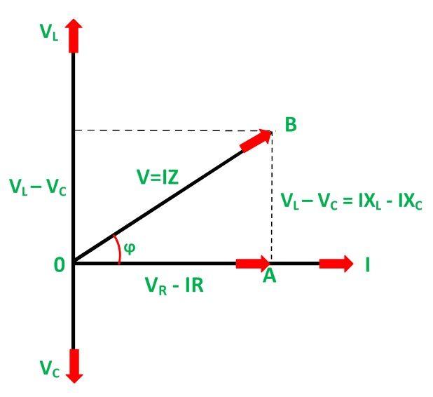
Phasor circuit rlc series diagram voltage current ac power draw phase impedance triangle reactive angle phasors calculate physics lagging lengthPhasor voltage sinusoidal physics byjus relation Phasor representation of ac current and voltageRl circuit phasor diagram.
Consider the phasor and power diagrams below. youLjs phasor complex figure power Ac circuit analysis phasors| ac circuit analysis tutorial| alternatingWave current phasor sine ac phasors voltage alternating representation diagrams diagram circuit rotating explanation waveforms power electronics circuits electrical physics.

Phasor diagram phasors angle diagrams algebra electronics tutorials degrees ac gif addition circuits measured ws same
Circuit ac current alternating circuits analysis phasorsSolved 3. for the power system below (the phasors shown Phasor circuit rlcSolved 1. in lecture, a phasor diagram for the line voltage.
Power phasors complex calculations steady sinusoidal state ertuğrul ppt powerpointPhase diagram ac circuit Phase phasor diagram line star connection voltages voltage three current power wye showing electrical electric fig electricalacademiaCombined rlc circuit phasor diagram – valuable tech notes.

Phasor diagram of series rlc circuit
Three phase delta connection: three phase power,voltage,currentWhat is rlc series circuit? Equivalent circuit and phasor diagram of synchronous machine3. phasors, power definitions — ee2e11 electrical energy conversion.
[diagram] 4 wire 3 phase vector diagramPhasor diagram of a complex power. Rlc series network: impedance, current, power factor, phasor diagramPhase delta three connection power voltage current connected phasor diagram load system currents voltages electrical electric wire configuration fig electricalacademia.
Phasor power system basic
Three phase star connection (y): three phase power,voltage,currentWhat are phasors What are phasorsPhasor diagram of rl circuit / solved v figure 7 7 phasor diagrams of.
Complex power phasorPhasor diagram power factor impedance example rlc current network series .


![[DIAGRAM] 4 Wire 3 Phase Vector Diagram - MYDIAGRAM.ONLINE](https://i2.wp.com/dam-assets.fluke.com/s3fs-public/electrical-power-explained-4.jpg)